In the fields of industrial automation and mechanical drive, speed regulating motors play a crucial role, and a correct understanding and mastery of the wiring diagram of speed regulating motors is the foundation for achieving their efficient and stable operation.

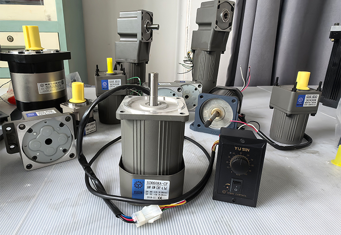
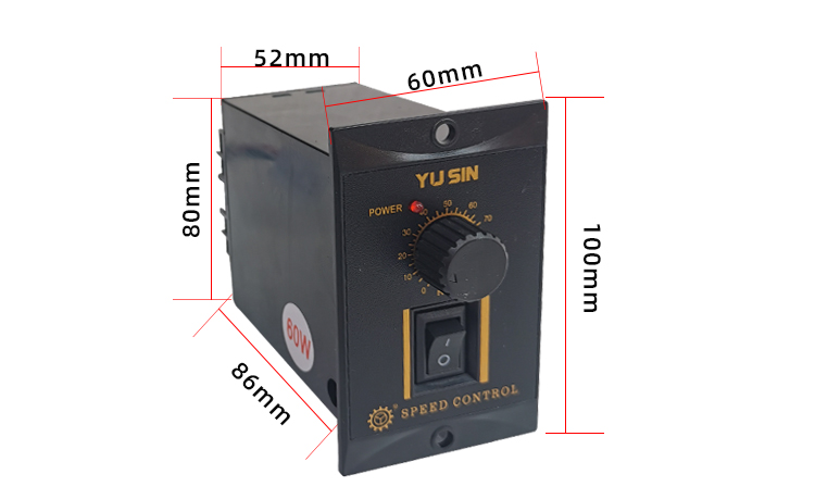
The motor terminal is a critical component that connects the speed controller to the motor. Proper connection ensures that the motor operates according to the parameters set by the speed controller. The speed control panel has power control buttons and speed control knobs. Through these buttons, operators can accurately adjust the motor's speed and operating status.
Connect the YUSIN small speed regulating motors speed controller through the motor interface and connect it to the speed regulating interface. Pay attention to the direction of the needle port and make sure it corresponds. Then connect the two AC ports of the speed regulating terminal to the single-phase 220V power supply, with the FG terminal as the grounding port. After connecting, turn on the power supply, turn on the switch on the speed regulating motor, and the motor will start running. Rotate the speed controller knob to adjust the motor speed.
In some AC three-phase speed control motor governors, it may involve the wiring of the frequency converter. The frequency converter converts fixed frequency AC power into a power supply with adjustable frequency and voltage, thereby achieving motor speed regulation. The wiring diagram will clearly indicate the connection methods for input power, output to motor circuits, and communication interfaces with control equipment.

However, in practical operation, wiring work must be strictly carried out according to the instructions of the wiring diagram, and it is necessary to ensure that the wiring is firm and the contact is good. Any incorrect connection can cause the governor to malfunction and even damage the equipment.
In short, the wiring diagram of YUSIN speed regulating motors speed controller is a key guide for achieving precise speed regulation and stable operation of the motor. Only by deeply understanding and accurately following the wiring diagram can the performance of the speed regulating motor speed controller be fully utilized, providing reliable power support and precise speed control for industrial production and mechanical operation.