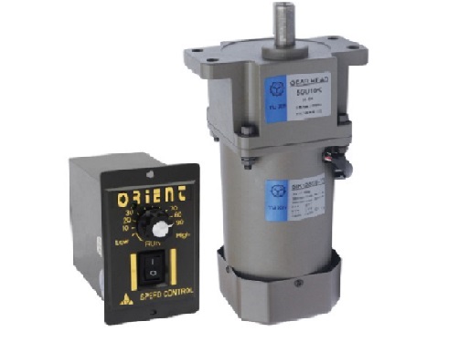
YUSIN Electromechanical has been focusing on the research and development of speed regulating motors for 17 years. This article provides professional electromagnetic speed regulating motor wiring principles and methods to users from the perspective of research and development technology, for reference only:
1. The U, V, and W of the motor are connected to the power supply through a contactor. 2. Connect to a 220V power supply. 3.4 (Two thick ones) Connect the excitation coil of the speed regulating motor (the front two terminals of the junction box on the left side of the motor are marked with numbers). 5.6.7 (U.V.W) is connected to the speed generator of the speed regulating motor (the three terminal posts behind the left junction box are marked with numbers). The speed controller is a seven hole aviation plug,

2. Motor connected to three-phase power supply A B.C, The wiring of the electromagnetic clutch of the motor, viewed from the shaft extension end of the speed regulating motor, from right to left, is 1.2 for the excitation coil (F1/F2) terminal, and 3.4.5 for the speed measuring generator (U/V/W) terminal.
3. The 7 wires on the controller aviation plug (governor): Terminal 1.2 is for 220V input, 3.4 is connected to the excitation coil on the governor motor, and 5.6.7 is connected to the speed generator on the governor motor. The detection of the quality of the full bridge is based on the fact that the full bridge is composed of four diodes, so the judgment of the quality of the full bridge can be obtained by separately detecting the quality of each diode. The method is to use the Rx1k or Rx1 Ω position of a multimeter, connect adjacent pins with red and black probes, and measure their forward and reverse resistance values. This way, four sets of forward and reverse resistance values can be measured. The forward resistance value is generally a few k Ω, and the reverse resistance value is close to ∞. If all of them meet this value, it indicates that the entire bridge is good. If one set of forward and reverse resistance values does not meet the requirements, it indicates that the entire bridge cannot be used. 2 Full bridge measurement: Place the meter in the R × 1K range, connect the black pen to the positive output pin of the full bridge, and connect the red pen to the other three pins respectively. The resistance value is infinite. Swap the meter probes and measure again. The resistance values are 3-6 kiloohms, 3-6 kiloohms, and 8-10 kiloohms, respectively. Similarly, if the black pen is connected to the negative output pin and the red pen is connected to the other three pins, the measured value will be the same as before. Swap the meter probes and the measured value will be infinite. If it does not match the ratio, it will be damaged! 3.1 Pin negative 2-pin positive/3-pin 4-pin AC input, 1-pin 2-pin set to 1k/negative probe connected to 1 positive probe connected to 2/AC input section, 8-10k Connect the negative probe to 3 and connect the positive probe to 4. When turned to 10k, it is infinite. speed regulating motors